I plan to design a mostly 3D-printable 6 axis arm similar to this for my final project. I believe I have the ability but haven't had the motivation to complete it in previous attempts,
so hopefully posting this here and sticking to a schedule will help. Completing a design would mean I would actually
build it (at some point).
Timeline Table
Week
Tasks
Week 10 (4/4 - 4/11)
Title/timeline
Week 11 (4/11 - 4/18)
Axis 1, Axis 2, journal entry
Week 12 (4/18 - 4/25)
Axis 3, journal entry
Week 13 (4/25 - 5/2)
Axis 4, journal entry
Week 14 (5/2 - 5/9)
Axis 5, journal entry
Week 14 (5/9 - 5/16)
Axis 5, journal entry
Week 16 (5/16 - 5/23)
Final submission, drawings, journal entry
I want to design it to have a minimum rotation rate of 15 RPM, so it takes at most 2 seconds to completely move most of
the axes.
Challenging tasks will be:
Ensuring 3D printed components have enough bracing or structure to support a decent load on the end.
Cycloidal gearboxes for reduction in at least the first two vertical axes (Axis 2 and Axis 3).
Gears and timing belt pulleys.
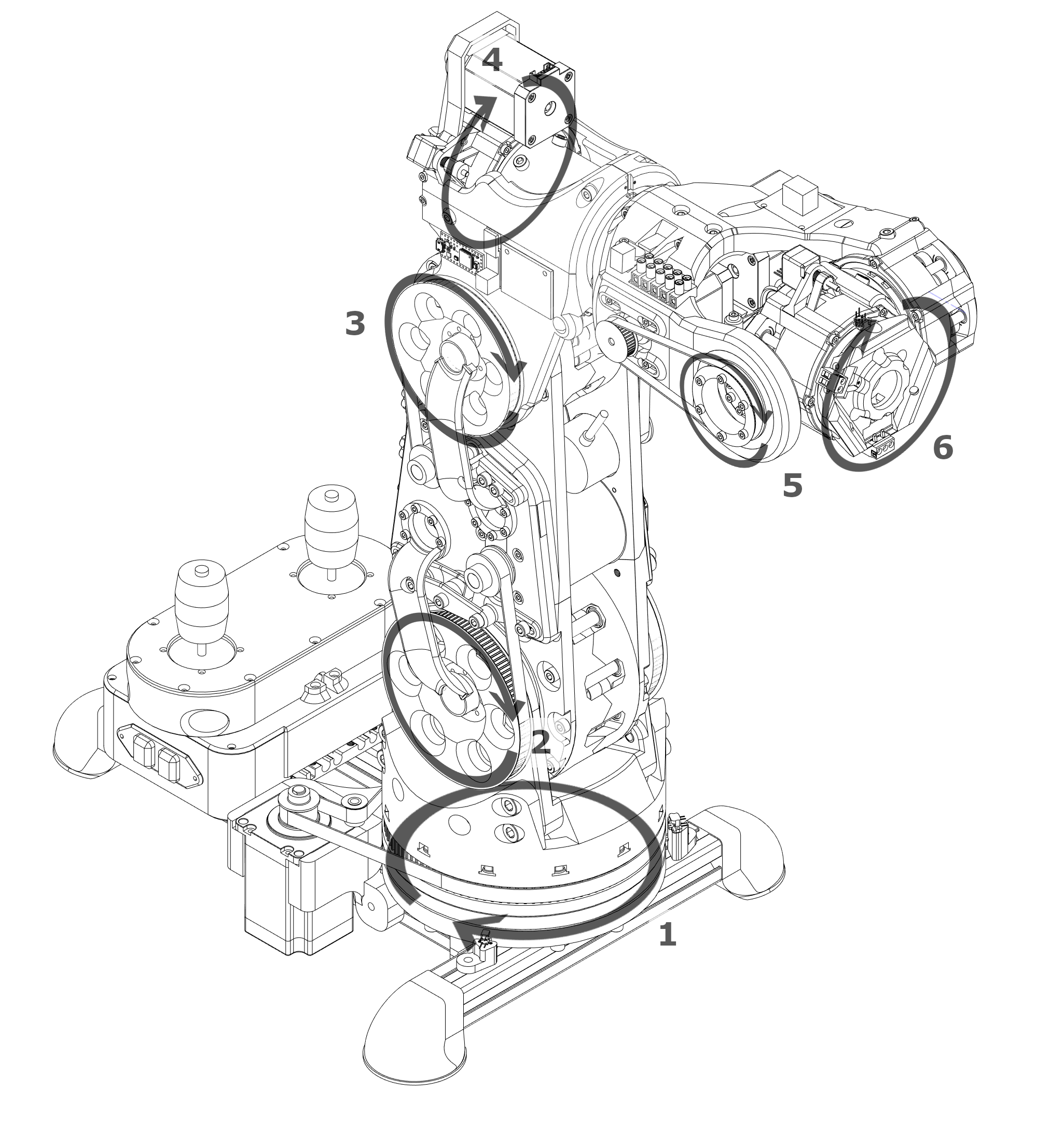
Wire management, especially on axes 1, 4, and 6, which can hopefully rotate infinitely. Slip rings for axes 1 and 4 will be useful, and the Atlas robot linked above has an interesting method for 5 and 6. A somewhat similar solution I had was to use a differential drive system. Wires would still need to pass through, though, for attachments. Another interesting idea from Atlas is using just two wires for the movement data, with drivers inside each axis.
Motor choice: Atlas robot uses 2 BLDC based servo motors in axes 2 and 3, but I might look into more cost-effective solutions. BLDC motors are difficult to drive precisely, requiring a $200 driver board for just the two axes. They move quite fast, meaning they need a reduction, improving precision. Stepper motors are cheap, and much easier to drive.
Stepper motors are quite precise on their own, but adding encoders to each axis will mean the robot can lose power, be moved, and still not destroy itself when it starts moving again.
I know that this is quite ambitious, so I guess a fall back would be a 4 axis arm, which is much simpler since three of the motors can be in the base. It would be much less capable than a 6 axis arm, though.
Question for the professor: I know that I will need to use off-the-shelf components like motors and hardware in this
project, so is it okay to download models, from sources like McMaster-Carr, or should I make them myself?
Response from Professor: Yes, very ambitious, but I like it a lot! Of course use McMaster!
Week 11 Entry
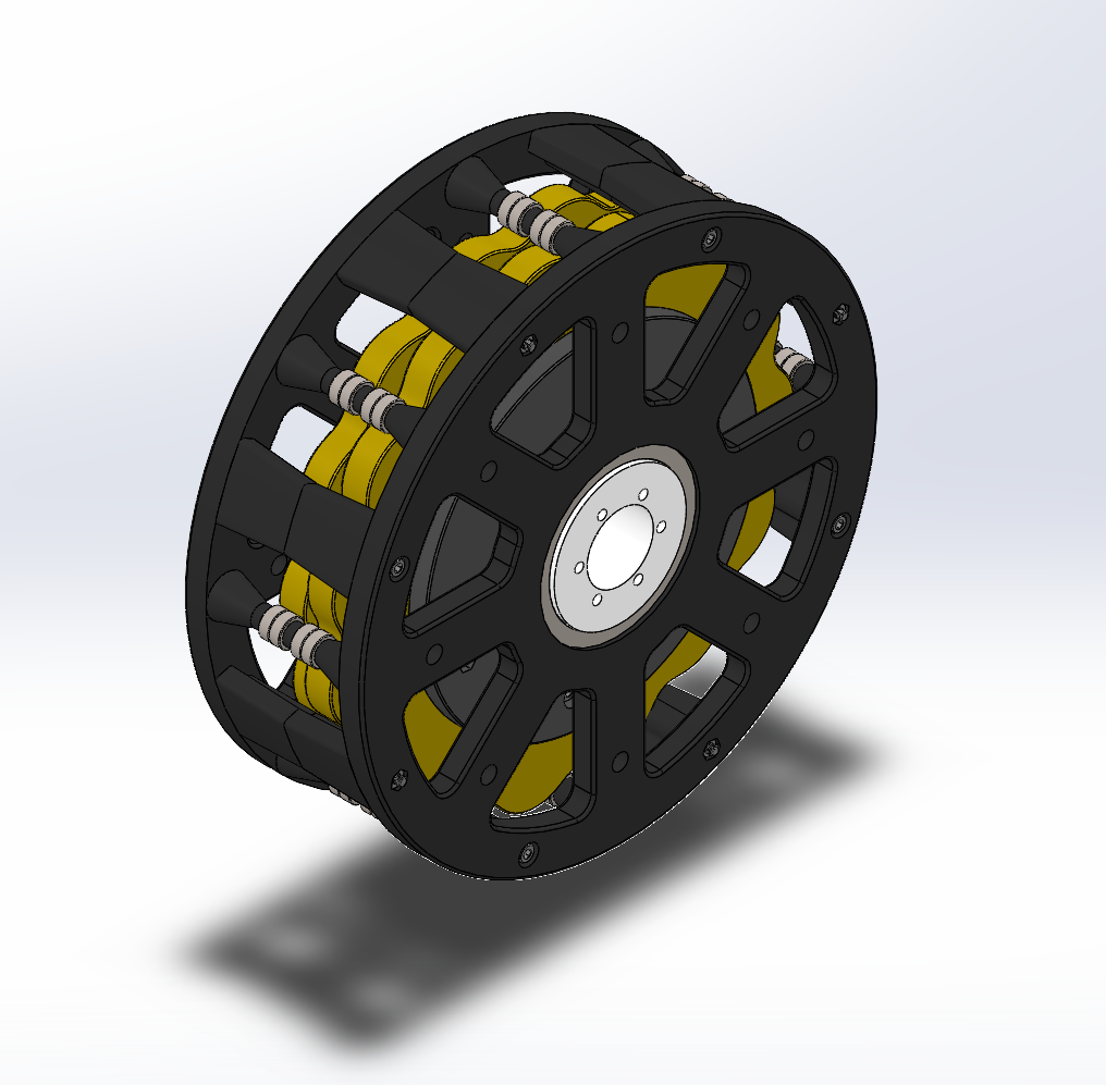
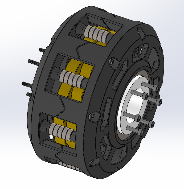
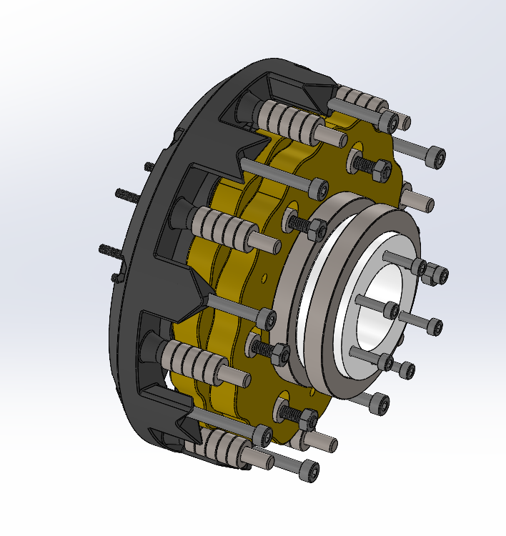
I fell behind on my plans this week, but I believe I finished one of the most difficult assemblies. I designed a 15:1
cycloidal reducer with a hollow shaft. There will be two of them on axes 2 and 3, for a total of 225:1 per axis.
I don't think this will be an issue for my plans, since this is the hard part of axes 2 and 3. Axes 1, 4, 5, and 6
should be simple compared to axes 2 and 3 since they will just use stepper motors, and hence can use belt or gear
reductions.
Over the next week, I will complete axes 2 and 3, and hopefully axis 1. This will keep me on track.
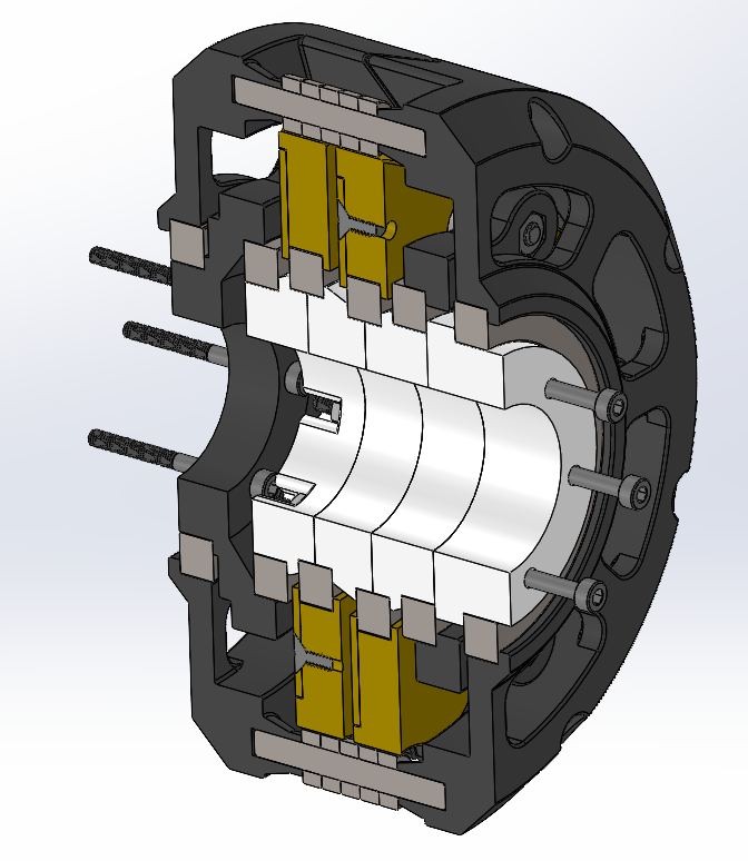
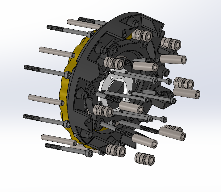
I followed this guide to model the cycloidal discs and the positions of the various rollers. I wasn't able to follow its guide for making the gearbox actually rotate correctly since the side of the cycloidal discs are actually two faces, but the output rollers are linked up properly. This will mean that my final arm assembly will not have the four gearboxes fully functioning. Anyways, I will likely remove all the internal components of the gearboxes so SOLIDWORKS can run at a decent speed. This assembly alone has 132 components.
Week 12 Entry
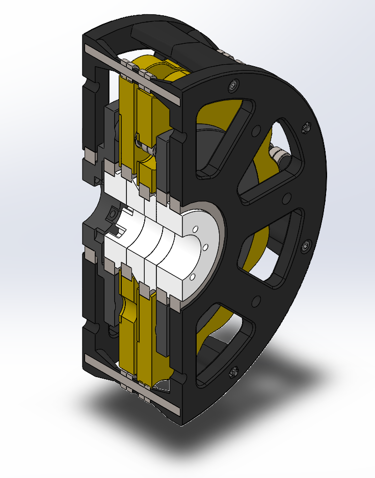
I fell behind again this week, and I realized that modeling a six-axis arm in the time we have for this project would lead to a half-baked and useless model, so I've decided to change my project to just a cycloidal drive. I already have a V1, but I'm unhappy with its bulkiness and the lack of fully defined motion in SOLIDWORKS. I think this is something I can truly polish and end up with a good final result.
I will be redesigning my cycloidal drive with a few goals:
Finding an alternative to an equation-driven curve for the cycloidal discs, that would allow for a cam-follower mate between the outer rollers and the discs.
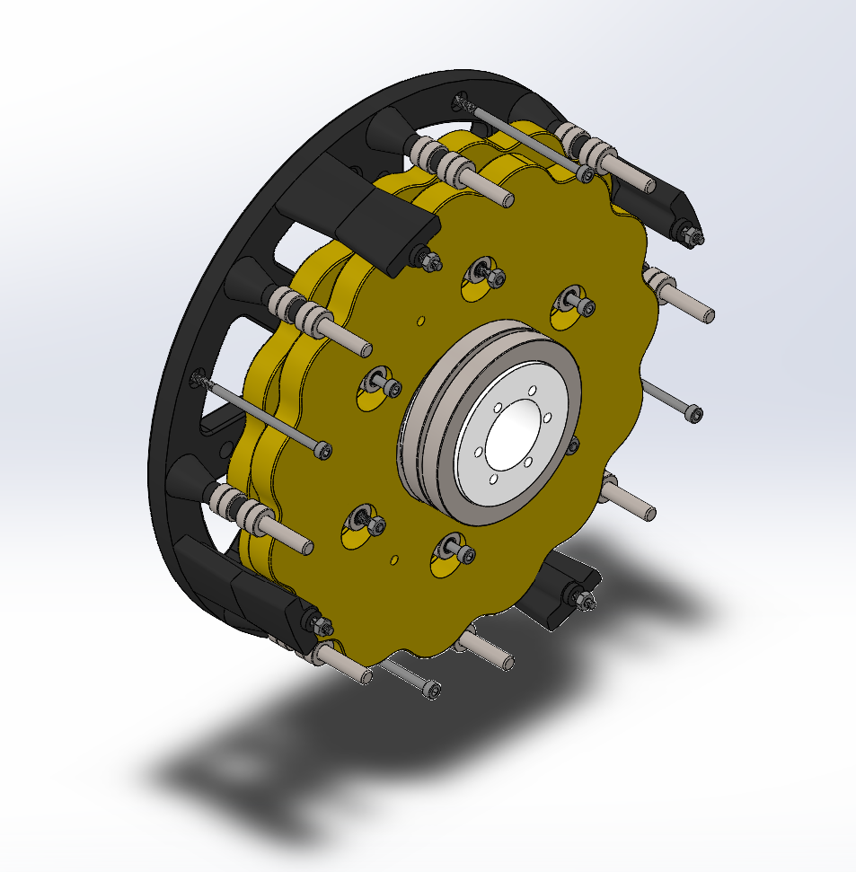
Replacing the bearings that are currently used for output rollers with bushings and pins, which will hopefully decrease the bulkiness.
Before I realized I should switch my project scope, I had redimensioned the cycloidal drive to work with the third axis.
Week 13 Entry
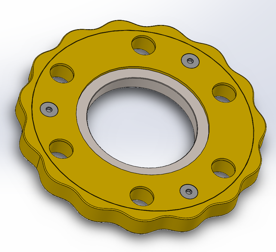
I've redesigned the cycloidal disk. I decreased the overall size, which was only possible because I decided to use 8mm steel spacers that will rotate on M4 bolts. This is preferable to simply using bolts because the threads could cause uneven wear on the plastic disks.
I've also discovered that I can have a sketch that contains the equation driven curves, and select both of them as a closed loop in the cam-follower mate. This should solve my problems with the gearbox not being fully functional.
Finally, I modeled both the main disk and the bearing cover in a single part with multiple bodies. I passed the CSWP exam this week and this was something I learned about in the training for it. Multibodies can be annoying, but they are really useful. I also used surfaces to create tolerances between the bodies, which was the only way I could find to add a real tolerance to the edge of the disk.
Week 14 Entry
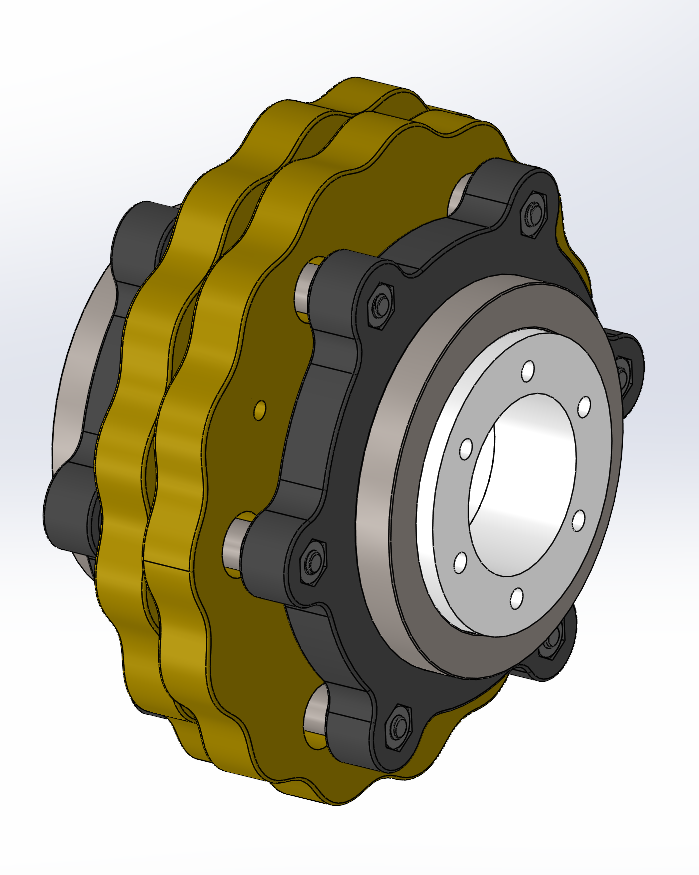
I've designed the output disks. I focused on creating them as configurations in a single part. It's not much, but I'm almost done with the project.
Week 15 Entry
The drive is complete! The drive functions, though it is implemented a bit backwards. It uses a Gear mate to drive the output from the input, and then uses tangent mates on the output rollers to drive the disks. Still, it fits perfectly. The path mate worked too, but it had problems with jumping around while spinning.
I tried to use a Motion Study to nicely animate the movement, but unfortunately, I was unable to figure it out in four hours. The animation, basic motion, and motion analysis options either errored out or simply did not animate correctly. Instead, I just screen-recorded myself spinning it to demonstrate its functionality.
What it's supposed to look likeWhat the motion analysis decided to create